Fire Response, Pipe Break and Shutdowns, and Control Overrides
Fire Response
Fire Response enables the user to place a fire demand (or other emergency flows) at a junction for a period of time to determine its impact on pressure and flows and possibly test alternative ways of responding to the fire. The user can reach fire response from the Home tab or the Emergency Response tab in SCADAConnect Simulator. This is to be used for simulating the operational consequences for a fire. For system wide fire flow capacity analysis, the user should use Fire Flow Analysis (see Fire Flow Analysis).
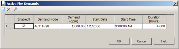
When the user picks Fire Response, a dialog appears. The user then picks the node where the fire flow is placed. Then the user completes the fire flow demand, start date/time and duration of fire demand.
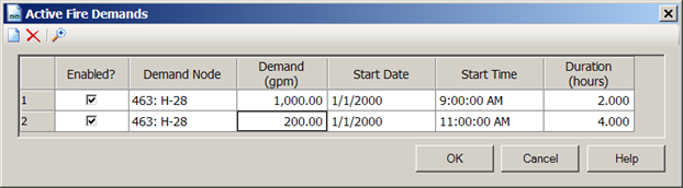
In some cases, fire fighters will use a large flow to control a fire for a few hours and then a lower flow to finally extinguish the fire. This would correspond to two entries in the Active fire flow dialog. An example of that setup is shown below.
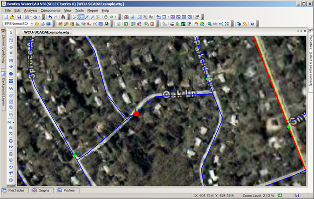
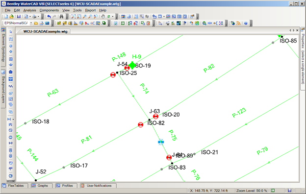
The image below shows the symbol for a fire placed on a hydrant element.
Pipe Break and Shutdowns
Pipe Breaks enables the user to specify a pipe break or a shutdown of a portion of the distribution system. (A shutdown is simply an isolated pipe break with zero leak flow.) The user can reach Pipe break simulation from the Home tab or Emergency Response tab of the SCADAConnect Simulator.
Pick the New button at the top of the Active Pipe Breaks dialog. This opens a row in the dialog shown below where the user can describe the break.
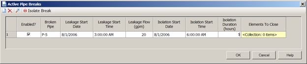
Enable indicates that this break is included in the scenario being run. The broken pipe is the pipe on which the leak is located. The user is prompted with a Select from Drawing dialog. The user should pick as accurate a leak location as possible because the leak symbol will be placed exactly at that location with respect of isolation valves. The exact leak location becomes important in determining how to isolate the leak. The pipe break simulation divides the duration of the run into the following time periods.
- Time before leakage start time when demands follow baseline scenario
- Time after leakage start but before isolation when leakage flow is added to the model and all pipes are in service
- Time after isolation start during isolation duration when isolated pipes have no flow and isolated nodes have no demand
- Time after isolation duration when flows return to values from baseline scenario
To define these times the user must specify leakage start date and time, isolation start date and time, and isolation duration. If the user is specifying a shutdown with no leakage, set the leakage flow to zero and the leakage start time doesn't matter.
The leak must be isolated for repair. To do this the user can either manually specify the valves and pipes to close or have the model pick the valves to close.
Manually picking the valves involves using the Select from Drawing toolbar button which will allow manual selection of the elements to close. Instead the user may wish to let the software decide which valves to close to isolate the pipe break. This can be achieved by clicking the Auto-Isolate button. The software will then populate the list of elements to close with those necessary to isolate the leak. At any time the user can choose to manually modify the automatically selected list and/or make additional manual selections. If it is known in advance that a particular valve or valves are not valid for isolation (perhaps a valve is known to be stuck open, or a particular control valve should not be closed for operational reasons) then the user may specify these elements by clicking the ellipsis button to the right of Elements to Exclude and selecting those elements. The next Auto-Isolation run will look for alternative valves to close.

Once the valves have been selected, the user can chose the highlight button (fourth button) to display the isolation. If the user is attempting to isolate a section of the system for repairs (e.g. pigging), the isolation valves must be manually selected.
If there are no isolation or other valves in the model in that part of the system, the user can select pipe elements to close. It is up to the user to ensure that these pipes do have sufficient valves to accomplish this isolation.
During the time that the leak (or maintenance event) is isolated, the flows in pipes in that area are zero and the demands are zero. The hydraulic grade and pressure in the isolated area will not have valid results.
Calculate Segment
With pipe break and shutdown events, you can calculate the segment that contains the event. The results will show the number of affected elements, isolation nodes, pipes, and affected customer meters. In addition, the results include the total segment length and water volume of the segment. The segment is automatically highlighted and zoomed for easy viewing. If there are any customer meters associated with the pipes in the segment, these will also be highlighted.
To calculate the segment, right-click the event and select "Calculate Break Segment" or "Calculate Shutdown Pipe Segment". Once the calculation completes, the results will be displayed, the segment highlighted and zoomed. It is also recommended that you turn on the highlight of the event as well to get the full effect of the highlighting of the segment.
Control Overrides
Control Overrides enables the user to modify controls on elements from those associated with the baseline scenario. For example, the user may instruct the model to force a pump to run for 3 hours starting at 4:00 am regardless of what the baseline scenario would have done. To set up a control override, pick the New button at the top of the Active Control overrides and pick which element is to be controlled, that property is overridden (e.g. for constant speed pump pick pump status and for variable speed pump, pick pump setting) , the value (On/off for constant speed, relative speed for variable speed pumps), the date and time when the override starts, the duration of the override and the priority if desired.
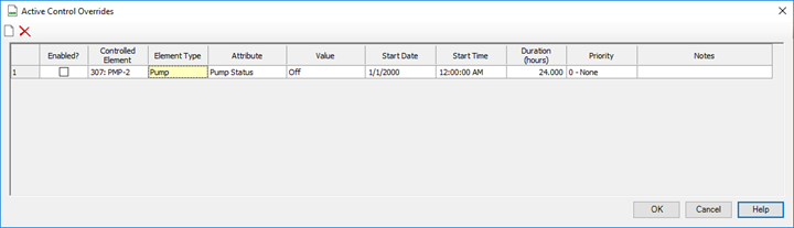
This can also be used to simulate a power outage by setting the pump status value to Off over some time period.
Custom Sorting
With control overrides, you can set a custom sort which is automatically applied when the editor is reopened and controls the order of the child nodes in the SCADAConnect Simulator structure.
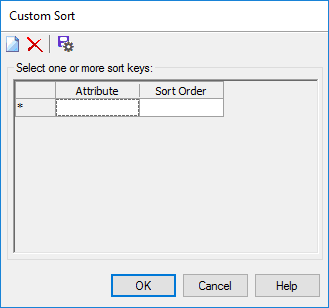
To set a custom sort order, right-click any column header (other than Value and Start Time), Sort->Custom. When the dialog comes up, select the columns and order you want to sort.
Once you have set the attributes and sort order, click the "Save As Default" button (last button on the right in the toolbar) to save this configuration.
This sort order is applied to the control overrides table and controls the order of the children of the Control Overrides node in SCADAConnect Simulator.
The custom sort defaults is global and applies to all WaterGEMS/WaterCAD projects and all calculation options for any scenario.
By default, the XML file that stores the custom sort does not exist. Until the user specifies a custom sort of their own the factory sort is automatically applied.
To reset back to the factory default sort order, make sure SCADAConnect Simulator is closed and delete the file: Haestad.Water.Forms.EditorModel.Collections.SCADA.ControlOverridesCollectionTableModel_sorts.xml in %UserProfile%\AppData\Local\Bentley\WaterGEMS\10.